
It is good to know that there are people who have tilt table layouts. In Nscale.net and Nscale.org, the forumers referred me to their fellow members who have tilt-table layout – Gene (aka epumph in Nscale.net) and the late Suzan (aka steamedup in Nscale.org). With Gene’s permission and in loving memory of Suzan, who passed away sometime ago, I would like to share with you their construction of a tilt-table layout and how you could adopt them for yours.
Gene (aka epumph)
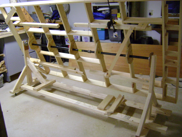
Gene from New Jersey, USA models a fictional Turtle Creek Industrial RR in N-scale on a 4ft 4in x 8ft 6in frame. Below is the frame in tilt position. Gene used 3/4in thick metal pole as axle/pivot to turn the layout either to the right or to the left. This gave him more flexibility to work on either underside of the frame.

From a 3/4in plywood, Gene created 5 pieces and nailed to the support beams. This way, the frame does not touch other parts of the base.

The support castor as Gene calls it is detachable.

The black pole as axle.

The tilt table in working position.


Three pictures showing the underside of the layout. The third picture shows an extension cord glued to the side on one support castor.

Gene’s Turtle Creek Industrial RR layout construction in progress with tilt table in “operating position”.
The late Suzan (aka steamedup)
Suzan was modelling a fictional Menasha and Fox River Valley RR on a 5ft x 9ft layout. Unlike Gene’s, Suzan’s was a static layout, as shown by the steel/aluminium brackets that supported the frame.


The frame in vertical “non working” position.

A cut-out of the layout to allow Suzan’s wheel chair to get closer to staging tracks (see trackplan below)

Menasha and Fox River Valley RR trackplan

Extra legs at each end to support the layout from tilting when in “operating position”

The brackets that allowed the table to tilt.


A full 180 degrees turn.

The steel/aluminium brackets to support the legs.
Well, I hope you are sold by the idea of a tilt table layout. At least I have. These modellers have shown how they did their layout out. In the case of Suzan, she was able to tilt her layout 180 degrees without needing to bend down to work on the wirings. For me, the prime motivation is space saving. Perhaps as I get old, the real benefit of a tilt table – the ability to tilt the benchwork and not having to bend down or crawl underneath to work on the wiring – would materialise.
I will have my frame in 2 equal frames of 1.2m x 1.2m with detachable support castors as Gene calls them, or support panels as I call them and make the whole piece transportable. Now I just need to add castor wheels to my second revised plan. Back to the drawing board and time to send the design to a few carpenters for quotation.

I am curious to know what is the actual width of the bottom pedestal with the casters. The standard door in North America is usually 30″ (76.2 cm).